MAPPING |
|---|
A GUIDE TO MAPPING WITH THE CINEFLEX MSII |

Introduction |
||
Many mapping systems claim to be easily integrated with any camera system but the reality is that it takes a special kind of integration to take full advantage of the power of the MSII. In this guide we explain the detailed workings of the Asset Management System (AssetMan) designed, built, and supported by Canberra based Analysis & Technology Australia. We've used the specific example of the electricity industry but of course the explanation is equally applicable to any industry that has to monitor a huge number of assets from the air. Please contact us if you would like a similar description of the Surveillance Mapping System (SurvMan II) which has been designed specifically for law enforcement agencies, fire authorities and so on. The more that we've worked with the companies responsible for transmitting electricity the more we've come to understand that a camera, however capable, is only the beginning of a work process that must seamlessly and efficiently flow into the existing IT infrastructure and work patterns of the client. It's no use producing reams of information in bespoke formats, and an image is utterly worthless if it has no associated metadata to pin it to a time and place. Enter AssetMan. |
||
 |
||
The AssetMan achieves the required seamless work flow and packages it as a total solution. The linesman inspecting the high definition and infra-red images now has a display of the exact point on the ground being inspected by the camera. Should he wish to rewind the imagery for a better look at something that's caught his eye then the mapping screen also rewinds, as does the imagery of the other sensor. Should he wish to record a line fault then he can fill out an online form and "paperclip" it to a still image, a detailed map or even a short piece of video. Alternatively all of this information can be combined into one file or image. The delight of the AssetMan is the way in which it's already designed to accommodate the bespoke and tailored requirements of different power companies. In the pages that follow we have set out to give as much information as possible on the various facets of the combined image and mapping solution we're offering. In many cases this is set out in the form of the questions we've been asked and the answers we've been able to give. We invite you to consider the extraordinary power of the MSII camera system and the associated Asset Management System and to ask yourself whether your current inspection techniques can offer you this level of efficiency and protection. |
||
Overview |
||
The AssetMan software application is housed on a ruggedised 3U MaxVision (www.maxvision.com) dual quad core Intel processor motherboard system that has been developed and qualified from existing systems. Although based on "commercially available" hardware, the various MaxPac systems are designed to be operated in extremely harsh environments and MaxVision have developed innovative solutions to overcoming issues such as board and plug retention in high vibration situations. The use of commercially available components enables the system to be utilized in demanding high end processing and video intensive tasks such as those encountered during inspection flight operations where searching, manipulating and updating of database information on potentially millions of assets can be achieved whilst displaying and recording camera HD video, at the same time as displaying and updating high definition imagery and maps as part of the underlying moving map. The AssetMan software has been developed around an extremely flexible and adaptable GIS engine that provides system compatibility with virtually all military and commercial maps, charts and imagery types or formats as well as compatibility with other system file sharing formats. This means that underlying mapping and display data can be imported or exported without the need for additional conversion utilities. Asset data can also be imported into the system via a number of different formats, the simplest are via ESRI Shapefiles or standard CSV files. This provides a system that is directly compatible with some of the import and export formats of other commonly used GIS software including GE SmallWorld. The system has been designed to import and export asset information without the need to provide it to a third party for conversion or manipulation. The system has the capability for customers' personnel to upload and download the data with a minimum of personal intervention. |
||
How are the Cineflex MSII and the AssetMan integrated? |
||
The AssetMan is designed to be fully integrated with the MSII. AssetMan receives both data and video from the camera system, and sends data to the camera system. With respect to data, AssetMan is connected to the camera system via an RS-232 serial port. AssetMan receives and uses, as a minimum, the following data generated by the camera: |
||
- Latitude |
||
| Camera aim point information |
||
- Latitude |
||
| AssetMan can send, on command, the following data to camera gimbal for pointing: |
||
- Latitude |
||
Additionally, AssetMan can take a video feed from the camera system (in either HD/SD SDI, or SD analogue) that can be displayed on the AssetMan screen as a picture in picture (PIP) of virtually any size up to full screen. The AssetMan operator can then capture this PIP along with the underlying map and asset information as a JPEG for post flight analysis and reconstruction purposes. The AssetMan system can also record the video for later replay if required. AssetMan has a underlying GIS software application that provides the geo- referenced display elements of AssetMan however AssetMan as a system provides significantly more that just the display of data. It is more akin to a spatial and infrastructure data management system where a database of assets and associated attributes including maintenance data can be recorded and manipulated through a visual front end. This front end provides geo-referenced display of the asset position against maps and other landmarks to permit ease of identification and validation of the correct asset. It also provides a quick and easy method to identify assets that are missing from the database and to capture their position for later validation and inclusion into the company asset listings. |
||
The actual tables and the associated input/output files and formats can be tailored to meet the customer's specific requirements. Certain fields within the tables are required to be provided however om general the fields are flexible and can be changed by the customer at any time given that a new database table is loaded over the existing one if additional attributes are added. The operator can search, select and centre on any asset contained within the database and then bring up the attributes etc for that asset. The system is unique in that it can operate in a fully "manual" mode for defect recording whereby the inspector selects the asset from visual reference on the display and enters/updates any information before moving to the next asset, or via a linked mode whereby AssetMan is linked to a camera system that provides a metadata feed which can be used to semi-automate some of the processes. In this mode when an asset is selected on the AssetMan screen, the positional data is passed to the EO system for pointing of the camera whilst the maintenance information on the pole is shown on the Assetman screen in order that it may be updated or additional defects raised. |
||
How are the terrain, infrastructure landmarks and other structures displayed? |
||
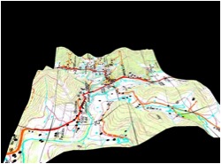
AssetMan can provide the operator with a number of display options for both the underlying reference data (map, chart, imagery etc) and for the display of data with respect to colors, shapes, symbology, hidden etc. Example 1 shows a base topographical map with a vector line (in dark blue), individual un-inspected assets (black dots), inspected assets (green dots), un-inspected assets in a operator designated inspection sequence (aqua dots on lines), selected waypoints and flight route (black crosses with green line) and an operator drawn area (red perimeter with blue cross hatching). This is a small example of possible combinations. |
||
 |
||
Example 1 |
||
| Example 2 shows a 1mtr imagery tile overlaid on a topographic map. Overlaying this are highways, major roads, streets and railroads all with separate colour coding. | ||
 |
||
Example 2 |
||
| Example 3 shows a static 3D snap shot (not dynamic for fly-throughs at this point) of the screen providing the operator with a quick view of the terrain overlaid on the elevation data and where assets , points, lines and areas are with respect to the terrain. For example does the asset line follow a valley or cross a ridge and so on can be seen easily by the operator in this mode. | ||
 |
||
Example 3 |
||
| To further assist in display item identification the operator may hide or display any of the layers (see blue and green push buttons middle left) including the underlying map in order to de-clutter the display, if required. | ||
 |
||
 |
||
| If a structure point or hazard is selected, the height can be seen as one of the attributes. As the pointer is hovered over the symbol, the base elevation is shown down in the bottom right of the screen along with the hazard latitude and longitude. The hazard label can also include description and height (i.e. Radio Mast 300 mtrs) giving the operator a quick visual reference if the label is turned on. |
||
 |
||
How does AssetMan allow for downloading capability to existing mapping systems via a ground based terminal? |
||
| AssetMan can download various sets of asset information/data or geo-referenced mapping or point/line/area data as required by the operator. In some cases the downloads (such as Shapefiles) are compatible with other standard GIS software and GE SmallWorld and as such may be downloaded direct to these systems even during flight via 3G or satellite communications. Data that can be downloaded post flight currently include such things as: |
||
- All asset defect data |
||
What would be a typical work flow for importing customer assets to the AssetMan? |
||
Although this can be altered to suit individual company requirements and methodology, the concept and work process flow are basically common. The company GIS division would generate a Shapefile of the assets to be loaded. The data is then loaded into Assetman. The maintenance (work order) file would be generated from the maintenance database and loaded directly into Assetman ready for operations. All of this can be completed by company personnel, meaning that corporate sensitive data never needs to be released to a third party. |
||
How does AssetMan allow for uploading from existing mapping systems via a ground based terminal? |
||
As mentioned earlier AssetMan can automatically upload virtually any format of geo- referenced maps/charts (raster or vector) or imagery for use as the underlying visual reference display. AssetMan can also upload such formats as Shapefiles for the display of points/lines and areas. This includes such things as landmarks, roads, waterways, railroads, assets, hazards and address layers etc. If unusual data is to be uploaded and the data has not been geo-referenced or requires some other transformation for uploading, then in general this can be completed on a ground based terminal and exported from the terminal in a suitable format. The most common transformation requirement relates to an aerial photograph or scan of a map that has not been geo-referenced such as a standard JPEG etc. These can be readily geo-referenced on a ground based terminal and saved as say an ECW or GeoTiff that can be readily imported into AssetMan. |
||
Is it easy for the customer to update or modify their asset lists? |
||
AssetMan is designed to enable as much flexibility as possible whilst still maintaining configuration management. From our understanding from other power companies, the asset data (position, description etc) may be held and maintained from a configuration control point of view by the company GIS section whilst the maintenance requirements and outstanding work orders are maintained by a separate maintenance section. This said, it is also important that the airborne operator and/or inspector can record changes in the data and new data in the air in a simple but fully cross referenced manner without impacting upon the validity of the original data held in the database. The operator can: |
||
|
||
The changes and the new asset data do not change the existing data but are tagged for download to the relevant authorities to verify and update the master database and for reissue by that authority. The operator can recall and view modified and existing data but cannot overwrite or change the original data. |
||
How does AssetMan allow for identification, marking and recording of new objects and hazards from the aircraft system controller? |
||
AssetMan can be used to plot and record positional and other data on designated points or assets. The operator can either enter positional data into AssetMan manually or can use a one press button whereby the position of the EO camera is used as the position. This also applies to lines and areas that can designated manually or captured through the use of the EO camera. The operator can then add attributes to the object position data and later export the data for inclusion in new databases for the company or other agency GIS for information. Example 1: If anyone in the aircraft saw a new hazard (a new unreported ham radio tower that has been erected by the land owner) that could impact upon safe line inspection or maintenance flying, then the operator could either enter the position manually (overfly for accurate GPS position) or use the camera to point to the base of the new radio tower and automatically capture the position. The tower position would be displayed on the AssetMan screen and the operator could also add attributes that would be recorded in the databases against the object. This data can be exported for further company or other agency use. Example 2: A scrub fire is spotted whilst an aircraft is on an inspection flight. The camera operator can outline the fire boundary and points along this boundary can be recorded and automatically joined to form an outline of the fire area. A Shapefile of the area can be exported and “emailed” from the aircraft using 3G or satcom for use by emergency services as the Shapefile can be automatically uploaded into their GIS to provide accurate data on the position and area size. Additionally this file can also be uploaded by the company GIS section to ascertain if any company assets are under threat. |
||
Does the mapping system stay with the aircraft on centre? |
||
AssetMan can be modified to operate in this mode (aircraft stabilized) however the use of ground stabilization with North up is a more natural way for operators to view maps or imagery that are used as the underlying reference in most cases. Additionally, in an aircraft centered mode, the computer resources needed to continually update underlying maps, asset positions, hazards, lines, areas and the EO camera position etc will significantly impact upon the ability of the system to carry out some of the tasks in a timely manner. A&T Australia has however implemented in AssetMan a mode that maintains the ground stabilization picture with the aircraft symbol transiting across the display in synchronization with the actual aircraft, however when the symbol approaches any edge of the displayed area, the aircraft symbol will automatically re-center on the display with the map and all plotted data updating accordingly. This continues unless the operator de-selects the auto-center mode whereby the aircraft symbol can “fly” off the screen. On the bottom right of the display is a touch button whereby the operator can, through one touch, at any time center the display on the aircraft or the EO Camera symbol position. |
||
Can AssetMan provide the camera operator with the ability to center on any loaded asset for rapid search and fly-to or tracking? |
||
AssetMan has facilities for the operator to center on: |
||
|
||
 |
||
Can AssetMan provide camera operators with the ability to automatically direct the camera to a designated asset position and show open work orders associated with that asset? |
||
When the operator selects an asset for inspection, there are a number of events that happen automatically. If the gimbal is set to receive directions from AssetMan it will slew to the position of the asset that has been passed to it by AssetMan, and additionally it will display the unique identifier of the asset on the camera monitor so that all captured video and stills can be easily associated with the asset. At the same time AssetMan will place a cursor over the asset to indicate that it is the one under inspection and it will also display any open work orders and/or will have a new work order form open ready to be completed if necessary. If there is work that needs to be raised the operator can enter it in the form or otherwise, if there is no requirement, the operator can select next to go to the next asset in a sequence list or just to close the form if no sequence list is in place. The asset symbol will change colour indicating that it has been inspected. If it is the wrong asset, the operator can just press cancel and it will close the box ready for the operator to designate the correct asset. |
||
 |
||
The on-board operator can add new defects through the New Work tab on the work order form. This can be in the form of a set defect selected from the pull down list or a free form comment. On saving, this new entry is recorded to the database against the asset identifier for later download. More than one new defect can be added against an asset. Additionally if the operators identify an asset that is not in the onboard database they can easily add it by pointing the EO camera at its position and then double clicking on any free spot on the AssetMan screen (i.e. not near another asset). This will bring up a form on which comments and defects can be raised then saved. This new asset information is saved into a separate database for downloading and validation before it is entered into the company GIS and hence updated onto a new version of the aircraft database. |
||
Please explain the ability to draw lines, points and set a polygon to indicate an impacted area using the camera reticule? |
||
| AssetMan provides the operator with the capability to: | ||
|
||
All points, areas and lines can be saved into various file formats for export during flight or after flight for uploading into other GIS software applications. The files may be exported during flight using 3G or Satcom or after flight using conventional methods of file transfer. |
||
 |
||
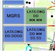
How does AssetMan display Latitude and Longitude? |
||
The operator may select the coordinate system for display from Military Grid Reference System (MGRS) to three different forms of Latitude and Longitude through the touch screen icons under the pull down menu. |
||
 |
||
The coordinates of the cursor position are displayed on the right bottom of the display including height of the ground at that point above mean sea level. |
||
The position and altitude of the aircraft are continually shown in the left bottom of the screen. Additionally, if required, Assetman can be configured to show coordinate grid on the display. |
||
What monitors would normally be used in the aircraft? |
||
The system can be used with virtually any standard high resolution monitor but through experience Analysis & Technology Australia has found that the use of the 17 inch Navpixel NPD1744 Sunlight Readable Marine Display has proven to be the optimum due to the fact that it is slightly lower in weight, is sunlight readable, provides multiple video inputs (all selectable for full screen or picture-in-picture), is reliable and is commercially available at reasonable cost. |
||
Conclusion |
||
We very much hope that you’ve found this guide helpful. Please don’t hesitate to contact us if other questions have occurred to you while reading this guide, or if you’d like an explanation that focuses on the specifics of your own industry |
||
|
||